10.8 Warnings and errors
This section gathers warnings and errors that can appear during QuickWave operation together with a description of when and why they appear, and how to eliminate them. The warnings and errors are grouped by topic.
QW-Editor
· Mesh
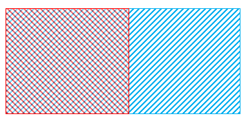
- Bit 1: Two identical edges forcing ambiguous media
This warning is displayed in QW-Editor Log and Project Info windows. It means that left edges of at least two elements/objects are overlapping and the media ambiguity appears, see picture below:
To avoid the ambiguity in red/blue region:
1. Left edge of red element/object may be split into two sections, creating two red elements/blocks. In such case, shorter tangential edges are treated as inner ones.
2. Boolean CUT operation on red and blue elements/objects may be performed.
3. The elements/objects should be drawn as adjacent not overlapping.
Note that the example below is unambiguous because red edge is shorter than blue edge and is treated as inner edge.
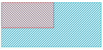
- Bit 4: Cell(s) with undefined medium
This warning is displayed in QW-Editor Log and Project Info windows. It appears in situations similar to those shown in the picture below:

The undefined regions are filled with the default medium or medium defined via optional file project_name.qm3.
The problematic cells may be viewed in Warnings Info window using Test Mesh functionality.
- Bit 8: Cell(s) with conflicting media
This warning is displayed in QW-Editor Log and Project Info windows. It appears in situations where cell edges force two or more media in the same region. An example is shown below. Black rectangle stands for a single FDTD cell. The central area of the cell contains conflicting red and blue materials.
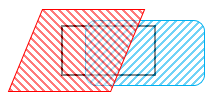
In such cases, geometry modifications or Boolean operations are necessary to avoid the conflict.
The problematic cells may be viewed in Warnings Info window using Test Mesh functionality.
- Bit 16: Cell(s) with undefined BOT medium
This warning is displayed in QW-Editor Log and Project Info windows. It is analogous to warning Bit 4 and appears for thin metal/metallic BOT layer.
The problematic cells may be viewed in Warnings Info window using Test Mesh functionality.
- Bit 64: Unresolved cell(s). Check exported structure with Test Mesh
This warning is displayed in QW-Editor Log and Project Info windows. It means that there is cell (or cells), which contains too many materials or conflicting data to determine its content unambiguously. Unresolved cell is filled with the default medium or medium defined via optional file project_name.qm3.
The problematic cells may be viewed in Warnings Info window using Test Mesh functionality.
- Bit 128: Half-homogenised cell(s). Check exported structure with Test Mesh
This warning is displayed in QW-Editor Log and Project Info windows. It appears for FDTD cells with “sandwich” medium layout. In such situations, those cells are resolved by eliminating one material. While solving this kind of FDTD cell, metal/metallic or central material has higher priority.
The problematic cells may be viewed in Warnings Info window using Test Mesh functionality.
- Bit 256: Repaired unresolved cell(s). Check exported struture with Test Mesh
This warning is displayed in QW-Editor Log and Project Info windows. It appears for a cell (or cells), which is filled with three different materials. In such cases, those FDTD cells are resolved in a way that their content is simplified to two dominant materials. While resolving the cell, metal and longer circumference material are preferred.
The problematic cells may be viewed in Warnings Info window using Test Mesh functionality.
- For V2D projects mesh must not extend below Y=0
This warning is displayed in a free-standing window. It appears during the export operation if any element/object/mesh extends below Y=0. The Y=0 plane is a lower boundary of the V2D circuits thus none element can extend below it. This warning prevents project export. To eliminate it, modifications in the project geometry or settings are needed.
- Too many cells along Z axis for V2D circuit
This warning is displayed in a free-standing window. It appears during the export operation if a height of any of elements/objects is bigger than 1 (corresponding to one FDTD cell). This warning prevents the project export because the V2D circuit cannot be higher than one FDTD cell (two half-cells). To eliminate this warning, modifications in the project geometry are needed.
- Mesh has changed during rotation
This warning is displayed in QW-Editor Log and Project Info windows. It may appear when QW‑3D is used with QW-BHM in the rotation routine. It appears when the AMIGO option is used for meshing. AMIGO enforces specific FDTD cell size in the object’s area. If the location of the object changes the overall project meshing changes too. This is signalised by this warning. The mesh generator checks the mesh after each rotation step.
- Mesh has changed during movement
This warning is displayed in QW-Editor Log and Project Info windows. It may appear when QW‑3D is used with QW-BHM in the movement routine. It appears when the AMIGO option is used for meshing. AMIGO enforces specific FDTD cell size in the object’s area. If the location of the object changes the overall project meshing changes too. This is signalised by this warning. The mesh generator checks the mesh after each movement step.
· Media
- Small permittivity or permeability value for medium “name” may cause instability
This warning is displayed in QW-Editor Log and Project Info windows. It appears when permittivity or permeability was set to be smaller than 0.9.
- Small losses and/or small time step and/or high permittivity for medium “name”. Losses may be neglected
This warning is displayed in QW-Editor Log and Project Info windows. It appears when the condition:
0.5*σ*Δt / ε > 1*10-7
where σ is conductivity in [S/m], ε is real permittivity in [F/m] and Δt is FDTD time step, is not obeyed. Materials where 0.5*σ*Δt / ε < 1*10-7 are treated as lossless ones.
Refer to Remarks section for more discussion regarding losses approximation.
- Small losses and/or small time step and/or high permittivity for medium “name”. Losses may be approximated inaccurately
This warning is displayed in QW-Editor Log and Project Info windows. It appears when the condition:
1*10-6 < 0.5*σ*Δt / ε £ 1*10-7
where σ is conductivity in [S/m], ε is real permittivity in [F/m] and Δt is FDTD time step, is fulfilled. Materials obeying the above condition are treated as lossy, but the losses may be approximated inaccurately.
Refer to Remarks section for more discussion regarding losses approximation.
- Small magnetic losses and/or small time step and/or high permeability for medium “name”. Losses may be neglected
This warning is displayed in QW-Editor Log and Project Info windows. It appears when the condition:
0.5*SIGM*Δt / μ > 1*10-7
where SIGM=sm/(k)4=wμ0μr”/(120p)2 is magnetic loss in [W/m], μ is real permeability in [H/m] and Δt is FDTD time step, is not obeyed. Materials where 0.5*SIGM*Δt / μ < 1*10-7 are treated as lossless ones.
Refer to Remarks section for more discussion regarding losses approximation.
- Small magnetic losses and/or small time step and/or high permeability for medium “name”. Losses may be approximated inaccurately
This warning is displayed in QW-Editor Log and Project Info windows. It appears when the condition:
1*10-6 < 0.5*SIGM*Δt / μ £ 1*10-7
where SIGM=sm/(k)4=wμ0μr”/(120p)2 is magnetic loss in [W/m], μ is real permeability in [H/m] and Δt is FDTD time step, is fulfilled. Materials obeying the above condition are treated as lossy, but the magnetic losses may be approximated inaccurately.
Refer to Remarks section for more discussion regarding losses approximation.
- Default METAL medium is non-PEC
This warning is displayed in QW-Editor Log and Project Info windows. It means that the type of the standard project medium “metal”, which is Perfect Electric Conductor, has been changed.
- Default AIR medium is non-standard
This warning is displayed in QW-Editor Log and Project Info windows. It means that the parameters of the standard project medium “air” have been changed (permittivity and/or permeability are not equal to 1 and/or conductivity and/or magnetic loss are other than 0).
· Other
- Reference plane is too close to circuit edge
This error is displayed in a free-standing window. It appears during the export operation when the S‑Parameters post-processing has been activated in post-processing dialogue and the distance between the reference plane and the circuit edge is smaller than 1 FDTD cell. With such reference plane position the differential method for S-parameters extraction cannot be applied. To eliminate this error:
1. S-Parameters post-processing may be deactivated if not needed.
2. The reference plane should be placed in at least one FDTD cell distance from circuit edge (one cell before and one cell after the reference plane are needed for differential method application). Note that one FDTD distance between the reference plane and the circuit edge is sufficient to apply the differential method but does not assure accurate S-parameters calculation. For accurate S-parameters extraction bigger distance of 4-5 FDTD cells, as given in S-Parameters, is recommended.
- Excited port number other than 1 for SK1
This warning is displayed in QW-Editor Log and Project Info windows. It appears during the export process if the S-Parameters post-processing in Sk1 regime has been activated and the source port has a port number different than 1. For proper S‑parameters extraction in Sk1 regime, the source port must have number 1.
- Load port number equal to 1 for SK1
This warning is displayed in QW-Editor Log and Project Info windows. It appears during the export process when either of the load ports in the project has port number equal to 1, which is reserved for source port. It may cause inaccurate S-parameters extraction. To eliminate this warning, the port number of all load ports should be other than 1.
- Port “name” is PML – not allowed for V2D project
This error is displayed in a free-standing window. It appears during the export operation if PML absorbing boundary conditions have been used in the V2D project. This error prevents the project export. PML absorbing boundary conditions are not allowed for V2D project, removing them from the project will eliminate the error.
- More than one source port for SK1
This warning is displayed in QW-Editor Log and Project Info windows. It appears during the export operation when more than one source has been included in the S‑Parameters post-processing in Sk1 routine, which requires only one source port. In the S-parameters calculation only source port with port number=1 is treated as a source, other source ports are treated as load ports.
- N I/O ports are named “name”
This error is displayed in a free-standing window. It appears during the export operation when there are N ports of the same “name” in the project. This error prevents the project export. To eliminate the error, all ports should have specific names.
- I/O Port reference number out of order
This error is displayed in a free-standing window. It appears during the export operation when the port reference numbers are out of the order or two references have the same number. This error prevents the project export. To eliminate it the reference numbers has to be consecutive integers, starting from 1.
- Invalid port size/location (Z above circuit/subcircuit)
This error is displayed in a free-standing window. It appears during the export operation when the meshed area has been manually limited by the user and the transmission line port has been placed along Z-direction beyond the meshed area. This error prevents the project export. It is advised to extend meshing area or change the port location so that it is placed in the meshed region.
- Invalid mesh (zero size along X, Y, or Z)
This error is displayed in a free-standing window. It appears during the export operation if the user attempts to export a project where no FDTD mesh has been defined. This error prevents the project export. The FDTD mesh must be defined to enable project export and simulation.
- Project-UDO parameters inconsistency
This warning is displayed in a free-standing window. It appears when redrawing the project with UDO, if UDO header contains different parameters than UDO script used for creation the object existing in the project. The reason for that may be modification of the UDO script or manual modification of *.pro file.
- Template effective permittivity less than zero for port “name”
This error is displayed in a free-standing window. It appears during the export operation when the effective permittivity of the transmission line port is below zero and prevents the project export. In typical operation this error should not appear since QW-Editor does not allow setting negative value for effective permittivity. This error may appear if the value of effective permittivity was changed by manual editing of *.pro file.
- Non-standard stability factor
This warning is displayed in QW-Editor Log and Project Info windows. It appears during the export operation to signalise that the stability factor has been modified upon user request and the FDTD simulation will be run with the FDTD time step corresponding to the new stability factor value.
- For axisymmetrical TM circular waveguide modes, MAGNETIC model of the axis must be used. Insert MAGNETIC mesh snapping plane at Y=0.
This warning is displayed in a free-standing window. It appears during the export operation for V2D projects if: angular variation= 0, the exciting field has been set to C_TMn1 or C_TMn2 and the magnetic symmetry plane is missing at y=0 plane. This warning prevents the project export. To eliminate it, the magnetic symmetry plane (magnetic mesh snapping plane) should be inserted at y=0.
- For axisymmetrical TE circular waveguide modes, ELECTRIC model of the axis must be used. Remove MAGNETIC mesh snapping plane at Y=0.
This warning is displayed in a free-standing window. It appears during the export operation for V2D projects if: angular variation= 0, the exciting field has been set to C_TEn1 or C_TEn2 and the magnetic symmetry plane is present at y=0 plane (while electric boundary conditions are required). This warning prevents the project export. To eliminate it, the magnetic symmetry plane (magnetic mesh snapping plane) at y=0 should be removed.
- BHM Movement – Multiple object assignment found
This error is displayed in a free-standing window. It appears during the export operation for BHM projects, if one object has been assigned to more than one rotation axis/movement trajectory. This error prevents the project export.
- Multiple object assignment found: Object "name" assigned to "rot1" BHM Rotation Axis/ "mov1" BHM Movement Trajectory and "rot2" BHM Rotation Axis/ "mov2" BHM Movement Trajectory
This error is displayed in QW-Editor Log and Project Info windows. It appears as a consequence of the “BHM Movement – Multiple object assignment found” error and contains additional information regarding the illegal assignment, by giving the name of object and rotation axes/movement trajectories to which it was assigned, what will help the user to eliminate the error.
- Basic Heating Module NOT allowed to use in V2D circuit
This error appears during the project export operation if the user is attempting to run microwave heating simulation using QW-BHM module for V2D circuit type. The microwave heating simulation with QW-BHM is available only for 3D circuits.
· MultiGPU
- Subregions borders are allowed in one direction only
This error is displayed in a free-standing window. It appears during the export operation if the division into subcircuits (subregions) have been made in more than one direction. The error prevents project export. To eliminate this error, the project should be divided into subregions only along one direction.
- Too narrow subregion slice
This error is displayed in a free-standing window. It appears during the export operation if any of the subregions along division direction is narrower than 3 cells. The error prevents project export. To eliminate it, the subregions borders’ location should be modified to assure that the subregions consist of at least 3 FDTD cells along the division direction.
- Border inside PML layer
This error is displayed in a free-standing window. It appears during the export operation if the subregions border has been placed inside PML layer, namely in the region limited with project boundary and the PML layer thickness. The error prevents project export. To eliminate this warning, the subregions border should be moved beyond the area corresponding to PML layer thickness.
- Border “name1” too close to reference plane “name2”. Shift one of them
This warning is displayed in a free-standing window. It appears during the export operation if the subregions border have been placed too close to or at the reference plane position. Note that if reference plane position does not coincide with a mesh line, it is eventually shifted to the E-field plane according to the rules given in Transmission line port excitation. This error prevents project export. To eliminate it, the subregions border or the reference plane should be shifted to increase the distance.
- Subregion border too close to project boundary. At least 3 cells are required to construct proper margin.
This error is displayed in a free-standing window. It appears if any of the subregion borders is located less than 3 cells from the project boundary. This error prevents the project export. To eliminate it, the subregion border should be shifted from the project boundary towards the circuit to assure at least 3 cells distance.
- Export impossible due to illegal position(s) of subregions border(s)
This error is displayed in a free-standing window. It appears as a consequence of other errors informing that the subregion border has been placed in a forbidden location, e.g. “Border inside PML layer”, etc. It is displayed after the proper error information and prevents the project export.
- QW-Simulator MultiGPU does not support FEATURE.
This warning appears when attempting to export the project or run the simulation with QW-Simulator MultiGPU simulator if one of the following not supported FEATUREs is active:
2DV circuit – when project is of 2DV or 2DVcoa (BOR) type,
3D Periodic circuit – when project is of 3DP type,
Plane Wave Box excitation – when the project contains the free space excitation with plane wave box,
Smn regime for S-Parameters postprocessing – when the S-Parameters post-processing in Smn regime is active in the project,
FD Monitor 2D – when Field Monitor 2D is present in the project,
ExH Time Integral postprocessing - when ExH Time Integral post-processing is active in the project,
NTF Fixed Angle postprocessing – when NTF Fixed Angle post-processing is active in the project.
This warning prevents simulation run.
- QW-Simulator MultiGPU does not support projects with subregion borders passing through or close to Ferrite material.
This warning appears when attempting to run the project in which subregion border passes through ferrite material or is placed too close ferrite object, and it prevents simulation run.
- Export discontinued. To see Test Mesh (including warnings map) for a project with subregions, export option “Suppress subregions export” is recommended. Test Mesh usage for individual subregions is possible (without warnings map) after manual loading of appropriate *.sh3 file.
This warning appears when the user attempts to invoke Test command for QW‑Simulator MultiGPU. The Test Mesh functionality is not available for projects divided into subregions. To be able to analyse the Test Mesh for such project, enabling “Suppress subregions export” in Export Options is recommended. If it is needed to analyse the Test Mesh of individual subregions, the user is advised to manually load appropriate *.sh3 file to QW-Simulator.
QW-Simulator
· Simulator Log window - Log Output
- ERROR: Inner/outer conductors have merged! Minimum 2 cells distance between conductors is required.
This error appears during the calculation of quasi-static template when the distance between inner (hot) and outer (ground) conductor is smaller than two FDTD cells. If the inner and outer conductors are separated by less than two FDTD cells, the QW-Simulator treats them as if they are merged and cannot calculate the quasi-static template. To eliminate this error it is required to return to QW-Editor and modify the meshing in a way that assures at least two cells of separation between conductors.
It may also appear when the condition for two cells distance between the conductors is obeyed and the TEM exciting mode is used to excite parallel plate line structure without introducing magnetic walls at structure’s sides (in one direction) to separate the electric conductors.
- F_central for USER_Pulse conversion failed (10 GHz assumed). Check the first line in user pulse file (e.g. !F_central=1.0)
This warning appears if the plane wave box (see Free space incident wave) excitation is with user defined waveform (see User defined signal excitation) and the central frequency has been incorrectly declared, e.g. !F_central=a. The declaration should be corrected otherwise central frequency equal to 10 GHz is assumed.
- This is Freeze with Rotation. Use ‘RunFreezeRot’ command for Rotation.
This warning appears when using the tasker mechanism (tasker/breakpoints commands) to unfreeze and run the microwave heating simulation, and the user is trying to unfreeze the *.sfr file, created for microwave heating with rotation simulation, with RunFreeze command. To assure correct simulation results, the RunFreeze command should be changed to RunFreezeRot command.
- Prony file does not exist: project_path
This error appears during Freeze operation for Prony simulation, when the *.prb file is missing in the project’s directory. Appearance of this error is hardly possible since the operating system should not allow for deleting of the *.prb file during the QW‑Simulator operation. If it appears, it may suggest operating system problems.
- Tasker file does not exist
This error appears during Freeze operation for QW-BHM project, if tasker file is missing in the project’s directory. Export operation performed in QW-Editor generates all the files required for running the simulation. If this warning appears, the *.ta3 file was probably manually removed from project’s directory.
- Parameters file does not exist
This error appears during Freeze operation for QW-BHM project, if parameters file *.pa3 is missing in the project’s directory. Export operation performed in QW-Editor generates all the files required for running the simulation. If this warning appears, the *.pa3 file was probably manually removed from project’s directory.
- Shape file does not exist
This error appears during Freeze operation for QW-BHM project, if shape file *.sh3 (main file or one of *.sh3 file generated for project with rotation) is missing in the project’s directory. Export operation performed in QW-Editor generates all the files required for running the simulation. If this warning appears, the *.sh3 file was probably manually removed from project’s directory.
- Pa3 file does not exist: project_path
This error appears during starting the simulation, if the parameters file *.pa3 is missing in the project’s directory. Export operation performed in QW-Editor generates all the files required for running the simulation. If this warning appears, the *.pa3 file was probably manually removed from project’s directory.
- Error saving simulator freeze file
This warning appears during the Freeze operation and may be caused by several reasons:
1. If the *.pa3 file is missing in project’s directory.
2. If *.sh3 file is missing in the project’s directory for QW-BHM projects.
3. If *.ta3 file is missing in the project’s directory for QW-BHM projects.
4. If the Freeze operation is made for QW-BHM scenario with frequency tuning.
- No S-Parameters postprocessing – Prony Module calculations unavailable
This error appears when the Prony Module calculations are invoked by the user, using Calculate_With_Prony tasker command, for a project in which S-Parameters post‑processing has not been activated. The solution is to enable the S-Parameters post-processing and Apply Prony method option.
- Excitation point on wire. Reference impedance self-adjusted to free space
This error is an unexpected error that should not appear in typical QuickWave operation. If it appears, please contact QuickWave support.
- Excitation point outside metal – hot conductor selected by the software!
This warning appears for quasi-static template mode if the excitation point is not placed at the conductor. In such case, the hot conductor is chosen by the software.
- Cannot find conductor edge! Application aborted with error code 1!
This error appears for quasi-static template mode if the space between conductors is filled with metal. In such case the quasi-static template mode cannot be generated and the QW-Simulator is aborted.
- Excitation point in metal of beyond symmetry plane! Check situation of excitation point (Test Mesh)!
This warning appears at the template mode generation stage, when QW-Simulator recognises that for the transmission line port with exciting field being Arbitrary or waveguide mode (dynamic template modes) the exciting point has been placed in metal or beyond symmetry plane if those are present in the project. To eliminate the warning, it is suggested to check and correct the location of the exciting port. This warning also appears if the background medium in e.g. waveguide fed antenna projects has been accidentally set to metal.
- ERROR: Wire radius (radius value) smaller than 0.022 cell (cell size). Calculations would be unstable! Plane XY: cell layer=K, cell ph=L, cell pv=M
This error appears if the radius of the wire is smaller than 0.022 of the adjacent cell size what causes that the calculations would be unstable. The corresponding radius value, cell size and the indexes of the FDTD cell are given in the error information content. To eliminate the error, the wire radius should be increased or the cell size should be decreased.
- Error: Wire radius (radius value) exceeds 0.91 cell (1). Calculation would be unstable! Plane XY: cell layer=K, cell ph=L, cell py=M.
This error appears if the radius of the wire is greater than 0.91 of the adjacent cell size what causes that the calculations would be unstable. The corresponding radius value, cell size and the indexes of the FDTD cell are given in the error information content. To eliminate the error, the wire radius should be decreased or the cell size should be increased.
- ERROR in Save_Waveforms: sources are not found!
This warning appears when the project without sources is run or the delta waveform has been chosen for the source. QW-Simulator by default saves to file the shape of the waveform of all sources present in the project. If there are no sources, there is no data to be saved and the warning appears. For delta, there is no time waveform to be saved.
- NTFFA postprocessing : theta should be in range [0 - 180 deg] - actual value: N
This warning appears if value for Theta angle set in the NTFFA post-processing dialogue in QW-Editor (N) is beyond the 0 – 180 degrees range. The spherical coordinate system limits the q angle range to 0-180 degrees.
- Cell size ratio for adjacent cells is more than 10 in K direction. Please consider reducing cell size ratio to obtain more accurate and stable results. ratio=N ink=M size1=L size2=R
This warning appears if QW-Simulator has detected that size of adjacent cells in K direction (K may be X, Y, Z) differs by a factor of 10 or more. The warning information gives the ratio of cells’ sizes (ratio), index of the first of problematic cells (ink, where k is the direction), and cells’ sizes (size). It is recommended to check the Mesh Inspect dialogue for cells’ geometry details and reduce the step in cell size in QW-Editor to assure accurate results.
· Simulator Log window – Warnings tab
- Reference and port plane are probably too close (K)! S-parameters extraction may not be accurate!
This warning appears if the distance between reference plane and the port plane in K direction, set in QW-Editor, is 3 FDTD cells or less. Such small distance may result in inaccurate S‑parameters extraction. For accurate S-parameters extraction the distance between the reference plane and the port plane should be increased (see Rule of thumb and hints for FDTD simulation in QuickWave for recommendations).
- Step in cell size across Reference plane (K-dir) detected! S-parameters extraction may not be accurate!
This warning appears if QW-Simulator detected that the cells before and behind the reference plane are of different size. The differential method of S-parameters extraction requires that at least one cell before and one cell behind the reference plane have the same size. This assures accurate S-parameters extraction. To eliminate this warning mesh modification in QW-Editor is required.
- No S-Parameters postprocessing! Can’t calculate Radiation efficiency.
This warning appears during the 2D radiation pattern extraction, when the radiation efficiency is calculated, if the S-Parameters post-processing has not been activated for the project. To eliminate this warning and enable radiation efficiency calculation, the S‑Parameters post-processing should be activated in QW-Editor.
- NTF frequency (N [GHz]) is not in the S-Parameters postprocessing frequency set! Can't calculate Radiation efficiency.
This warning appears during the 2D radiation pattern extraction, when the radiation efficiency is calculated, if NTF frequency N does not coincide with the frequency points set for S-parameters extraction. In such case the radiation efficiency cannot be calculated for frequency N and 0 value is displayed in the Results window. To eliminate this warning and enable radiation efficiency calculation, the frequency step for S‑Parameters post-processing should be chosen to assure that the S-parameters are calculated for all NTF frequencies.
- No FD-Probing postprocessing! Can’t calculate Radiation resistance.
This warning appears during the 2D radiation pattern extraction, when the radiation resistance is calculated, if the FD-Probing post-processing has not been activated for the project. To eliminate this warning and enable radiation resistance calculation, the FD‑Probing post-processing should be activated in QW-Editor.
- NTF frequency (N [GHz]) is not in the FD-Probing postprocessing frequency set! Can't calculate Radiation resistance.
This warning appears during the 2D radiation pattern extraction, when the radiation resistance is calculated, if NTF frequency N does not coincide with the frequency points set for FD-Probing post-processing. In such case the radiation resistance cannot be calculated for frequency N and 0 value is displayed in the Results window. To eliminate this warning and enable radiation resistance calculation, the frequency step for FD-Probing post-processing should be chosen to assure that the FD-Probing is calculated for all NTF frequencies.
- No FD-Probing postprocessing! Can’t calculate Current injected by source.
This warning appears during the 2D radiation pattern extraction, when the current injected by source is calculated, if the FD-Probing post-processing has not been activated for the project. To eliminate this warning and enable current injected by source calculation, the FD‑Probing post-processing should be activated in QW-Editor.
- NTF frequency (N [GHz]) is not in the FD-Probing postprocessing frequency set! Can't calculate Current injected by source.
This warning appears during the 2D radiation pattern extraction, when the current injected by source is calculated, if NTF frequency N does not coincide with the frequency points set for FD-Probing post-processing. In such case the current injected by source cannot be calculated for frequency N and 0 value is displayed in the Results window. To eliminate this warning and enable current injected by source calculation, the frequency step for FD-Probing post-processing should be chosen to assure that the FD-Probing is calculated for all NTF frequencies.
- No S-Parameters postprocessing! Can’t calculate Power injected by source.
This warning appears during the 2D radiation pattern extraction, when the power injected by source is calculated, if the S-Parameters post-processing has not been activated for the project. To eliminate this warning and enable power injected by source calculation, the S‑Parameters post-processing should be activated in QW‑Editor.
- NTF frequency (N [GHz]) is not in the S-Parameters postprocessing frequency set! Can't calculate Power injected by source.
This warning appears during the 2D radiation pattern extraction, when the power injected by source is calculated, if NTF frequency N does not coincide with the frequency points set for S-parameters extraction. In such case the power injected by source cannot be calculated for frequency N and 0 value is displayed in the Results window. To eliminate this warning and enable power injected by source calculation, the frequency step for S‑Parameters post-processing should be chosen to assure that the S-parameters are calculated for all NTF frequencies.
- F_central (central frequency) for delta excitation problem : 10.0 assumed
This warning appears if the waveform for excitation with plane wave box (see Free space incident wave) has been set to delta. The plane wave box excitation requires determining a central frequency. Since it is missing for delta, 10GHz is assumed by the software.
- F_central (central frequency): illegal pulse type: 10.0 assumed
This warning appears if the waveform for excitation with plane wave box (see Free space incident wave) has been set to step pulse. The plane wave box excitation requires determining a central frequency. Since it is missing for step pulse, 10GHz is assumed by the software.
- F_central (central frequency): for USER PULSE is set to 10.0 GHz
This warning appears if the waveform for excitation with plane wave box (see Free space incident wave) has been set to be a user defined waveform (see User defined signal excitation). The plane wave box excitation requires determining a central frequency. When using user defined signal excitation, the file with excitation waveform should have a declaration of the central frequency (see User defined signal excitation). If the declaration is missing, central frequency at 10GHz is assumed by the software.
- NTFFA postprocessing : theta should be in range [0 - 180 deg] - actual value: N
This warning appears if value for Theta angle set in the NTFFA post-processing dialogue in QW-Editor (N) is beyond the 0 – 180 degrees range. The spherical coordinate system limits the q angle range to 0-180 degrees.
- Two ports: “name1” and “name2” are partially overlapping!
This warning appears if two ports of different kind (e.g. MUR wall and PML wall) are overlapping. The obtained results may be inaccurate. It is recommended to modify the project in QW-Editor to avoid ports overlapping.
- Two ports: “name1” and “name2” (source) are partially overlapping!
This warning appears if two ports of different kind are overlapping and one of them is a source port (e.g. MUR wall and Plane wave wall). The obtained results may be inaccurate. It is recommended to modify the project in QW-Editor to avoid ports overlapping.
- NTF wall “name”: out of range along Z dir
This error appears if any cell indexes included in NTF wall “name” (“name” may be XY1, XY2, XZ1, XZ2, YZ1, YZ2) along Z direction, coincide with the project boundary. The obtained 2D radiation pattern results are incorrect in such case. It is required to modify the project in QW-Editor so that the NTF walls are located in some distance from the project boundary (see Rule of thumb and hints for FDTD simulation in QuickWave for recommendations).
· Error/Warning Dialogue
- Lower frequency for port “name” is greater than lower frequency for postprocessing. S-parameters extraction may not be accurate
This warning appears while opening Results window for S-parameters if the lower frequency set for S-Parameters post-processing is smaller than the lower frequency of the exciting pulse. In such case the S-parameters extraction may not be accurate. It is recommended to modify the S-Parameters post-processing settings or the excitation frequency range in QW-Editor.
- Upper frequency for port “name” is less than upper frequency for postprocessing. S-parameters extraction may not be accurate
This warning appears while opening Results window for S-parameters if the upper frequency set for S-Parameters post-processing is greater than the upper frequency of the exciting pulse. In such case the S-parameters extraction may not be accurate. It is recommended to modify the S-Parameters post-processing settings or the excitation frequency range in QW-Editor.
- Lower frequency for port “name” is greater than lower frequency for postprocessing. FD-Probing parameters extraction may not be accurate
This warning appears while opening Results window for FD-Probing if the lower frequency set for FD-Probing post-processing is smaller than the lower frequency of the exciting pulse. In such case the FD-Probing parameters extraction may not be accurate. It is recommended to modify the FD-Probing post-processing settings or the excitation frequency range in QW-Editor.
- Upper frequency for port “name” is less than upper frequency for postprocessing. FD-Probing parameters extraction may not be accurate
This warning appears while opening Results window for FD-Probing if the upper frequency set for FD-Probing post-processing is greater than the upper frequency of the exciting pulse. In such case the FD-Probing parameters extraction may not be accurate. It is recommended to modify the FD-Probing post-processing settings or the excitation frequency range in QW-Editor.
- Tasker break! Pa3 file does not exist: project_path
This error appears during starting the FDTD simulation if project_name.pa3 file is missing in the project directory. Export operation performed in QW-Editor generates all the files required for running the simulation (*.sh3, *.pa3, *.ta3). If this error appears, the *.pa3 file was probably manually removed from project’s directory. It causes that the FDTD simulation will not run. It is advised to export the project from QW-Editor once again.
- Shape file (*.sh3) does not exist. Application aborted with error code 1!
This error appears during starting the FDTD simulation if project_name.sh3 file is missing in the project directory. Export operation performed in QW-Editor generates all the files required for running the simulation (*.sh3, *.pa3, *.ta3). If this error appears, the *.sh3 file was probably manually removed from project’s directory. This error aborts QW-Simulator. It is advised to export the project from QW-Editor once again.
- Incorrect *.sh3 file format detected! FileName
This warning appears if the user attempts to load to QW-Simulator *.sh3 FileName file which has incorrect file format.
- Incorrect 1D Fields file format detected! FileName
This warning appears if the user attempts to load to QW-Simulator *.den, *.de3 or *.tpd FileName file which has incorrect file format.
- Incorrect 2D/3D Fields file format or file version detected! FileName
This warning appears if the user attempts to load to QW-Simulator *.dmp, *.tpl, *.vi3, *.ve3, *.fe3 or *.fi3 FileName file which has incorrect file format.
- Incorrect MonitorFields file format detected! FileName
This warning appears if the user attempts to load to QW-Simulator *.fm3 FileName file which has incorrect file format.
- Incorrect 3D Radiation Pattern file format detected! FileName
This warning appears if the user attempts to load to QW-Simulator *.an3 FileName file which has incorrect file format.
- This is file format for external program read only! FileName
This warning appears if the user attempts to load to QW-Simulator *.vi3 or *.ve3 FileName file which has been saved with Dense_Regions_Only option.
- Can’t find ‘*cell descr’ in proper place in *sh3 file – file format error. Application aborted with error code 1!
This error appears if *.sh3 file read by QW-Simulator is incorrect. This may be cause by issues during the project export from QW-Editor. This error aborts operation of QW-Simulator. If it appears, please contact QuickWave support.
- Tasker break! Template frequency has not been found. Check Template mode searching frequency range or Periods for field pattern generation.
This warning appears when QW-Simulator fails in generating the mode template for transmission line port with exciting field being Arbitrary or waveguide mode (dynamic template modes). QW-Simulator informs that there was a problem with finding required template matching frequency. It is advised to check settings in I/O Ports Parameters (or Edit Transmission Line Port) dialogue in QW-Editor. Two possible reasons for this problem to appear are: incorrect definition of Template mode searching frequency range (e.g. the searching range does not cover template matching frequency) or too small value of Iterations for eigenvalue search.
- Only one multiTEM conductor! Application aborted with error code 1!
This error appears if the distance between conductors and transmission line port edges for multiTEM excitation is less than 2 FDTD cells. For such small distance the QW‑Simulator recognises only one conductor and cannot generate quasi-static multiconductor TEM template mode. In such situation, QW-Simulator will be aborted. To eliminate the error, modification of the meshing in QW-Editor is required.
- Nonlinear materials require GPU device supporting double precision. Aborting simulation.
This warning appears if FDTD project with nonlinear material has been run with GPU version of QW-Simulator and the double precision for calculations is not supported by the GPU card or has not been enabled for it. In case of nonlinear materials, to ensure correct simulation results, higher calculations precision is required. Double precision for FDTD calculations performed on GPU card can be enabled in Configure®Preferences®GPU window. Older GPU cards might not support this functionality. In such case it is advised to use other QuickWave simulator.
- Tasker File Not Found! For freeze file – check version! Can’t Start Simulator
This error appears during starting the FDTD simulation and may have several different reasons. It aborts FDTD simulation. If it appears, please contact QuickWave support.
· MultiGPU
- Currently Basic Heating Module is not supported in QW-Simulator MultiGPU. Use other QuickWave simulator.
This warning appears if the user attempts to run BHM simulation with MultiGPU version of QW-Simulator. The Basic Heating Module is not implemented in MultiGPU simulator and the simulation will not run. It is advised to use other QW-Simulator version.
- Currently S-Parameters postprocessing in Smn regime is not supported in QW-Simulator MultiGPU. Use other QuickWave simulator.
This warning appears if the user attempts to run FDTD simulation with S-Parameters post-processing in Smn regime using MultiGPU version of QW-Simulator. The Smn regime for S-parameters calculation is not implemented in MultiGPU simulator and the simulation will not run. It is advised to use other QW-Simulator version.
- Currently ExH Time Integral postprocessing is not supported in QW‑Simulator MultiGPU. Use other QuickWave simulator.
This warning appears if the user attempts to run FDTD simulation with ExH Time Integral post-processing using MultiGPU version of QW-Simulator. The ExH time integral calculation is not implemented in MultiGPU simulator and the simulation will not run. It is advised to use other QW-Simulator version.
- Currently NTF Fixed Angle postprocessing is not supported in QW‑Simulator MultiGPU. Use other QuickWave simulator.
This warning appears if the user attempts to run FDTD simulation with ExH Time Integral post-processing using MultiGPU version of QW-Simulator. The ExH time integral calculation is not implemented in MultiGPU simulator and the simulation will not run. It is advised to use other QW-Simulator version.
- Eigen value solver postprocessing is not supported in QW-Simulator MultiGPU. Use other QuickWave simulator.
This warning appears for projects, which contain Eigen value solver postprocesssing. This postprocessing is not supported in MultiGPU version of QW-Simulator and the simulation will not run.
- Fields Monitor 2D postprocessing is not supported in QW-Simulator MultiGPU. Use other QuickWave simulator.
This warning appears for projects, which contain Fields Monitor 2D postprocesssing. This postprocessing is not supported in MultiGPU version of QW-Simulator and the simulation will not run.
- Currently excitation with Plane Wave box is not supported in QW-Simulator MultiGPU. Use other QuickWave simulator.
This warning appears if the user attempts to run FDTD simulation with Plane Wave Box excitation using MultiGPU version of QW-Simulator. The excitation with Plane Wave Box is not implemented in MultiGPU simulator and the simulation will not run. It is advised to use other QW-Simulator version.
- Currently only 3D circuit type is supported in QW-Simulator MultiGPU. Use other QuickWave simulator.
This warning appears if the user attempts to run FDTD simulation for V2D circuit type with MultiGPU version of QW-Simulator. The V2D circuit type is not supported in MultiGPU simulator and the simulation will not run. It is advised to use other QW-Simulator version.
- Currently periodic circuit type is not supported in QW-Simulator MultiGPU. Use other QuickWave simulator.
This warning appears if the user attempts to run FDTD simulation for 3D periodic circuit type with MultiGPU version of QW-Simulator. The 3D periodic circuit type is not supported in MultiGPU simulator and the simulation will not run. It is advised to use other QW-Simulator version.
- Dimensions of Field Monitor box are out of bounds. Skipping postprocessing.
This error is signalised by QW-Simulator MultiGPU if the Field Monitor box was incorrectly exported by QW-Editor. If it appears, please contact QuickWave support.
- Subregion border cannot cross ferrite.
This warning appears when the user attempts to run FDTD simulation with MultiGPU version of QW-Simulator, for a project with ferrite material, if the subregion border crosses the object made of ferrite medium. Such scenario is illegal and the simulation will not run. To eliminate this warning it is advised to locate the subregion border in QW-Editor in some distance from the object made of ferrite material.
- Project with subcircuits cannot be proceeded with this simulator! Use QW‑Simulator MultiGPU instead.
This warning appears if project divided into subregions is run with QW-Simulator other than Simulator MultiGPU. Projects with subcircuits can be run only with MultiGPU version of QW-Simulator.
- Project version is too old for multiple subcircuits in QW-Simulator MultiGPU (QW_3D parameters file v1.9 required). Use QW-Editor v2016 or newer.
This warning appears if the user attempts to start the FDTD simulation with QW‑Simulator MultiGPU from *.ta3 or *.pa3 files, which were exported using QW‑Editor v2015 or earlier. MultiGPU version of QW-Simulator requires parameters file *.pa of version 1.9 or higher and this is exported with QW-Editor v2016 or newer.
- Fatal error during subregion’s transfer configuration!
This error is fatal QW-Simulator MultiGPU error. If it appears, please contact QuickWave support.
- Inconsistency in subcircuit connections description
This error is fatal QW-Simulator MultiGPU error. If it appears, please contact QuickWave support.
- Inconsistency between circuit and subcircuit parameters
This error is fatal QW-Simulator MultiGPU error. If it appears, please contact QuickWave support.
· QW-BHM
- BHM Heat transfer processing not started – Thermal conductivities are zero
This error appears when using internal Heat Flow Module, if *.pmo file does not contain thermal conductivity values or they are 0, and no alternative declaration has been made in Media dialogue in QW-Editor and the default 0 values have been kept.
- BHM Heat transfer processing not started – Specific heat or Density is zero
This error appears when using internal Heat Flow Module, if *.pmo file does not exist and specific heat or density value set in Media dialogue in QW-Editor is 0. The specific heat and density are used in HFM time step calculation. If any of them is 0, their product is 0 and HFM time step is 0 and heat transfer cannot be performed.
If the error appears for project with *.pmo file, please contact QuickWave support.
- Error “code” occurred during BHM Heat transfer processing
This error may be caused by several reasons. The error “code” indicates the cause explicitly. If the error appears, please contact QuickWave support.
- Error #2 occurred during BHM Rotate processing – specified .sh3 file does not exist
This error appears if the *.sh3 file for a specific position of the heated object is missing in the project directory. For each position of the heated object corresponding to the object’s rotation, QW-Editor exports a separate *.sh3 file. If any of the *.sh3 files is missing in the project directory, it might have been deleted manually. It is recommended to perform the export operation in QW-Editor once again.
If an appropriate *.sh3 file is missing in the project directory, microwave heating for a given BHM step cannot be performed.
- Min temp/Max temp - Not found (search region for T min should be set by setting non - zero density of media)
This information appears in the Simulator Log window if none of the heated loads has non-zero density. The Min/Max temperature values are searched among lossy regions with non-zero density. To enable finding Min/Max temperature in the heated objects, their density defined in *.pmo file or in Media dialogue in QW-Editor, should be bigger than 0.
- ParamK or Parama < 0 in the pmo file: PMOname
This warning appears if value of parameter ParamK (parameter Param in K direction) or Parama given in the *.pmo file is negative. The Param parameter can be: EP (permittivity), MU (permeability), SIG (conductivity), MSIG (magnetic loss), K (thermal conductivity); and K may be: X, Y or Z. The ParamK stands for parameters of anisotropic media. The Parama stand for parameters of isotropic media and may be: EPa, MUa, SIGa, MSIGa, Ka. If this warning appears it is advised to verify the *.pmo file.
- Density < 0 in the pmo file: PMOname
This warning appears if QW-Simulator detects negative value of Density the *.pmo file. It is advised to verify the *.pmo file content.
- SpecHeat < 0 in the pmo file: PMOname
This warning appears if QW-Simulator detects negative value of specific heat in the *.pmo file. It is advised to verify the *.pmo file content.
- Enthalpy < 0 in the pmo file: PMO name
This warning appears if QW-Simulator detects negative value of Enthalpy in the *.pmo file. It is advised to verify the *.pmo file content.
- Thermal conductivity K < 0 – illegal value
This warning appears if there is no *.pmo file defined for the heated load and thermal conductivity in K direction value set in QW-Editor is negative. This warning aborts Heat Flow Module processing. It is advised to verify the thermal conductivity values.
- No Temperature column in pmo file. Initial Enthalpy value will be set at 0
This warning appears if the *.pmo file does not contain the temperature column. In such situation the initial value for enthalpy will be set to 0.
- Header column number and numeric column number are not matched in pmo file PMOname
This error appears if the number of header columns (parameters’ declaration) and the number of numeric columns (parameters’ values) in the *.pmo file are different. It is advised to check if any parameter declaration is missing in the header while its numeric values are included in the file or if numeric values of any of the declared parameters are missing. This error aborts QW-Simulator.
- Illegal value in pmo file PMOname
This error appears if any of the variables present in the *.pmo file (PMOname), except for temperature, has negative value. This error aborts QW-Simulator. The *.pmo file should be modified and illegal negative values should be removed to eliminate this error.
- No temperature neither enthalpy found in pmo header file PMOname
This error appears while using Heat Transfer Module if temperature and enthalpy are missing in the header of *.pmo file. This error aborts QW-Simulator. To eliminate it, *.pmo file should be appropriately modified.
- Illegal keyword in the pmo file PMOname
This error appears if QW-Simulator detects illegal name for header column in *.pmo file. This error aborts QW-Simulator. The format of the *.pmo file is given in Basic Heating Module: Interactive operation and the file should be appropriately modified to eliminate the error.
- Illegal number format in pmo file PMOname
This error appears if QW-Simulator detects in *.pmo file a different number of value rows for parameters’ column. All the parameters should have the same number of values, thus all columns should have the same number of rows. It is advised to modify the *.pmo file appropriately.
· QW-OptimiserPlus
- No S-Parameters in Smn regime postprocessing
This error appears if the QW-OptimiserPlus was configured to optimise the S-Parameters post-processing in Smn regime and the Smn option was not activated for the analysed project in the QW-Editor. The error aborts QW-OptimiserPlus operation and the optimisation will not run. It is advised to activate the Smn regime in QW-Editor, save the project and run the optimisation once again.
- No S-parameters postprocessing
This error appears if the QW-OptimiserPlus was configured to optimise the S‑Parameters post-processing and this post-processing was not activated for the analysed project in the QW-Editor. The error aborts QW-OptimiserPlus operation and the optimisation will not run. It is advised to activate the S-Parameters post-processing in QW-Editor, save the project and run the optimisation once again.
- No FD-Probing postprocessing
This error appears if the QW-OptimiserPlus was configured to optimise the FD‑Probing post-processing and this post-processing was not activated for the analysed project in the QW-Editor. The error aborts QW-OptimiserPlus operation and the optimisation will not run. It is advised to activate the FD-Probing post-processing in QW-Editor, save the project and run the optimisation once again.
- No NTF postprocessing
This error appears if the QW-OptimiserPlus was configured to optimise the Near to Far (NTF) post-processing and this post-processing was not activated for the analysed project in the QW-Editor. The error aborts QW-OptimiserPlus operation and the optimisation will not run. It is advised to activate the NTF post-processing in QW‑Editor, save the project and run the optimisation once again.