
Home > QW-Modeller > QW-Modeller Manual > 9 Patch Antenna Array
9 Patch Antenna Array
A patch antenna array consists of Nx × Ny individual patch antennas, arranged in a rectangular grid, separated by spacing of Sx and Sy, in X and Y direction respectively, and located at a margin of Mx and My from substrate edges. Patch antenna arrays can be modelled in QW-Modeller as a finite sized Nx × Ny patch array on a defined size substrate. Each separate patch antenna is excited by a point port, placed in the middle of substrate height, joint with the wire connecting the patch and ground beneath the substrate. The direction of main radiation beam can be automatically steered by defining θ and φ angles, for which QW-Modeller calculates two-dimensional progression of the excitation signal delay (corresponding to phase shift) within all patch antennas.
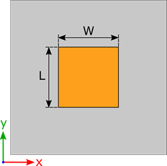
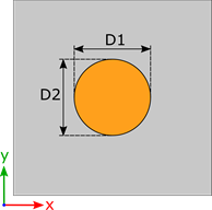
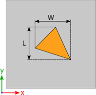
Definition of individual patch dimensions indicated for: rectangular patch, circular patch, and user-defined patch geometry.
Patch antenna array with Nx=4 and Ny=3.
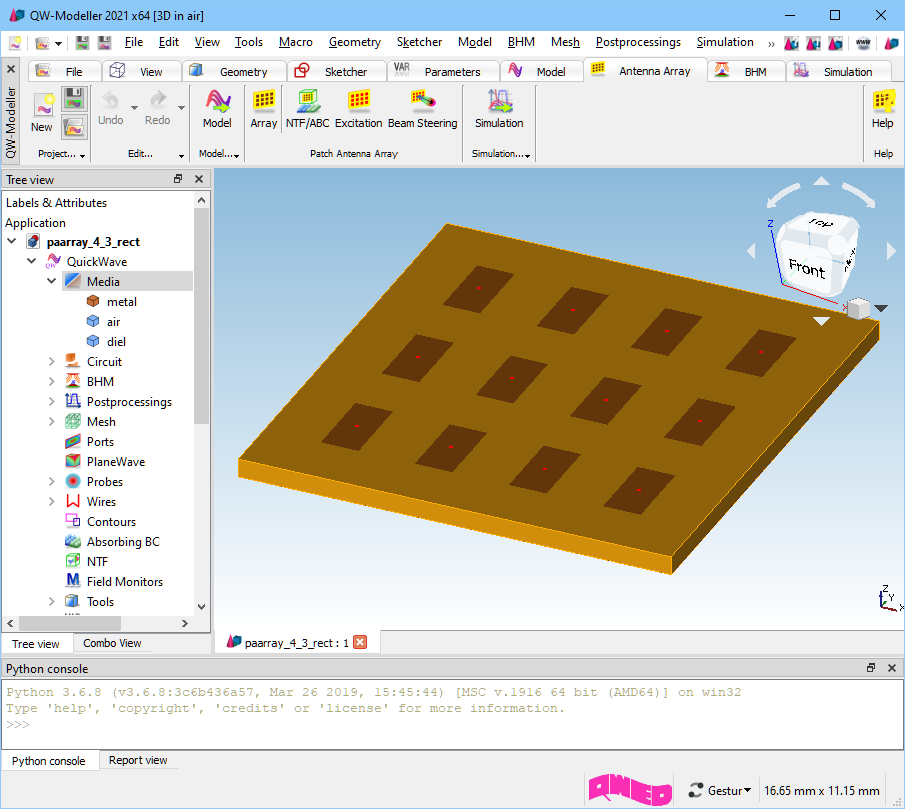
The structure of patch antenna array can be defined in Patch Antenna Array dialogue.
The absorbing boundary conditions and required radiation pattern settings for the patch antenna array scenario can be defined in Patch Antenna Array – NTF/ABC Settings dialogue.
The excitation signal settings of patch antenna array can be defined in Patch Antenna Array – Excitation dialogue.
The beam steering configuration can be made in Patch Antenna Array – Beam Steering dialogue.
Home > QW-Modeller > QW-Modeller Manual > 9 Patch Antenna Array