
2.24 Port Change
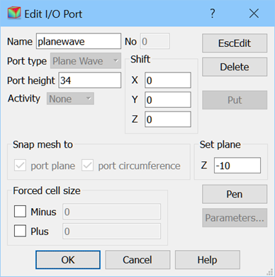
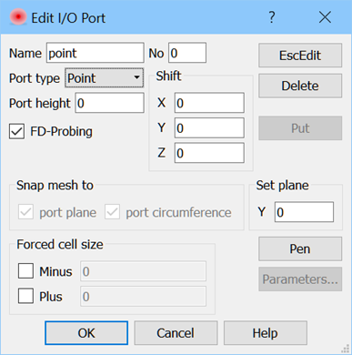
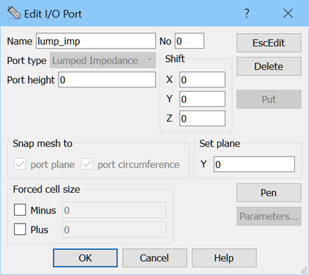
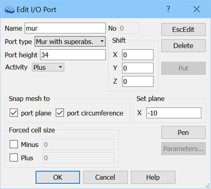
The Edit I/O Port dialogue allows changing position and parameters of ports and can be invoked from Select Element dialogue or from Edit Port or Edit Element context menu.
We suggest more convenient way of changing position and parameters of I/O ports using a set of dedicated dialogues. See I/O Ports chapter for more information.


Edit I/O Port dialogue allows changing the basic parameters for transmission line ports, point ports, plane wave boxes, lumped impedances and absorbing walls and boxes. Note that in the case of Transmission Line Port the Shift operations move the port together with its reference plane (in the case of S-Parameters ports, which are denoted by No. field higher than 0).
Activity command allows changing orientation of the port. For example it is natural that a port defined at the left edge of the structure will assume the circuit to be on the right and the software will make such a default assumption. However if we choose a port inside the structure an ambiguity appears. In this case the default choice can be corrected here by the user.
Set plane allows verifying the position of the port in the direction perpendicular to it. We can set another position. The advantage with respect to doing this with a mouse in 2D Window is that we can be sure that the position of the port in the cross-section of the line has not been changed.
Shift allows moving the port by a certain distance in the direction of each of the three axes. Note that in the case of reference planes, shift will only be allowed along the transmission line.
EcsEdit exits the dialogue and escapes the the Edit Port or Edit Element mode (the cursor in the 2D Window return to arrow). OK or Cancel exit the dialogue but do not escape the Edit Port or Edit Element mode (the cursor in the 2D Window remains square).