2.21.4 Edit Element
The ![]() button in the 2D Window toolbar and Edit->Edit Element command from 2D Window menu are used for changing position and parameters of the selected item (can be element, wire or port).
button in the 2D Window toolbar and Edit->Edit Element command from 2D Window menu are used for changing position and parameters of the selected item (can be element, wire or port).
First we must move the local coordinate system to the correct level by using Define Level or Select Element dialogues (only items with LevelZ being at the Z-coordinate of the current local coordinate system will be captured). After Edit Element command is invoked, the cursor changes from arrow ![]() to square
to square ![]() indicating the Edit mode. Now approach the item to be changed with the cursor. To move the item, press left mouse button, drag it by moving the mouse, and press left mouse button to fix a new position.
indicating the Edit mode. Now approach the item to be changed with the cursor. To move the item, press left mouse button, drag it by moving the mouse, and press left mouse button to fix a new position.
Note that to get out of the Edit Element mode we can press E on the keyboard.
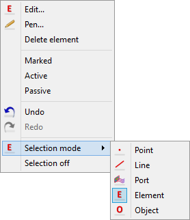
Press right button to access the element change context menu with the choice of several operations:

Edit… - depends on the kind of the selected item, open:
· Element Change dialogue for simple element and wire grid
· Edit I/O Port for port
· Edit Wire for wire
· Edit Special Plane, Boundary… for NTF, Field Monitor and Mesh Snapping Planes and Subregion Borders
Pen… - open Select Pen dialogue for changing the item display colour in QW-Editor
Delete element - delete selected item
Marked - mark or unmark selected element for Reproduce operations
Active - set as active element for Join operations
Passive - set as passive element for Join operations
Undo - permits to revoke up to N moves in QW-Editor
Redo - revokes up to N Undo commands
Selection mode - allows choosing other type of selecting mode
Selection off - abandons the currently selected mode (cursor returns to arrow)