6.1.9 Mesh Snapping Planes and Symmetry Planes
The ![]() button in the 2D Window toolbar and Draw->Special Planes/Boundaries... command from 2D Window menu invoke Special Planes and Boundaries dialogue which can be used for drawing Special (Snapping) Planes, Symmetry Planes or Boundaries in a manual way.
button in the 2D Window toolbar and Draw->Special Planes/Boundaries... command from 2D Window menu invoke Special Planes and Boundaries dialogue which can be used for drawing Special (Snapping) Planes, Symmetry Planes or Boundaries in a manual way.
We suggest alternative and more convenient way of introducing the Special (Snapping) Planes, Symmetry Planes or Boundaries using Snapping Plane dialogue.
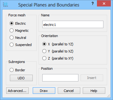
The most frequently used application of this dialogue will be to force mesh through the introduction of a Mesh Snapping Plane. It is like indicating a plane to which the FDTD mesh must adjust:
· Electric forces cell edges i.e., a plane whereat the tangential electric field components are calculated,
· Magnetic forces cell centres i.e., a plane whereat the tangential magnetic field components are calculated,
· Neutral forces either Magnetic or Electric plane, depending which distorts the existing mesh to a lesser extent,
· Suspended sets an additional plane between the FDTD mesh planes whereat additional geometry information will be extracted for better approximation of complicated shapes at subcellular levels.
Technically mesh snapping planes work like a port without executing the input/output functions. Note that in the case of Mesh Snapping Planes the size of the rectangle introduced to mark the plane is of no importance. It is displayed only to recall to the user where the plane is. The user should make it of the size least disturbing to the images of the structure or even choose the white colour to make it invisible. A keyboard shortcut Shift+M moves the x- and y-mesh snapping planes to the boarders of the project and normalises their lengths of the displayed markers to a standard cell sizes.
The right part of the dialogue allows fast inserting of Mesh Snapping Planes. Only Orientation needs to be selected and one coordinate (Position) needs to be specified, and after pressing Insert button QW-Editor will draw the plane with default dimensions and colour.
Subregions group allows creating Subregion Border(s) that are used in MultiGPU version of QW-Simulator. Border option allows drawing Subregion Border manually or automatically insterting it at the defined position and UDO button allows automatic drawing from UDO script. Subregion can be suppressed for export in the Export Options dialogue.
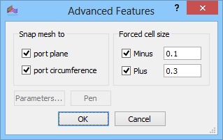
The Advanced… button invoke Advanced Features dialogue which can be used for snapping mesh options and user defined cell size can be enforced in the negative and positive directions from the special plane by checking Minus and Plus check box and introducing the cell size.
The Electric snapping plane can be used as an electric boundary conditions (which are the default boundary conditions ) applied at the borders of the circuit. They may serve also as the symmetry planes as in the One dipole near electric wall example.
The Magnetic snapping plane can be used as a magnetic boundary conditions and may be enabled at the borders of the circuit. They may serve also as the symmetry planes as in the One dipole near magnetic wall example. In case of QW-V2D, those are the default boundary conditions applied at y=0 (r=0).
We suggest alternative and more convenient way of introducing the Special (Snapping) Planes, Symmetry Planes or Boundaries using Snapping Plane dialogue or by using special UDOs available in the UDO Library.