Home > QuickWave Editor > 7 FDTD Mesh > 7.2 Snapping Plane
7.2 Snapping Plane
The ![]() command from Add section in
command from Add section in ![]() button in Model tab and Mesh->Mesh Snap->(Add) Snapping Plane... command from main menu invoke Snapping Plane dialogue for adding mesh snapping plane.
button in Model tab and Mesh->Mesh Snap->(Add) Snapping Plane... command from main menu invoke Snapping Plane dialogue for adding mesh snapping plane.
This dialogue can be also opened for adding or editing the mesh snapping plane from Snapping Planes dialogue.
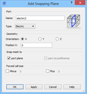
The name of the mesh snapping plane can be set in Name field. The Type drop-down list allows determining if the snapping plane should be of type electric or magnetic. In the Parameters frame, the user declares along which axis the snapping plane should be placed and its position (Position field).
If the port plane is checked, the mesh line will be enforced at snapping plane position.
User defined cell size can be enforced in the negative and positive directions from the special plane by checking Minus and Plus check box and introducing the cell size.
The most frequently used application of this dialogue will be to force mesh through the introduction of a mesh snapping plane. It is like indicating a plane to which the FDTD mesh must adjust:
Electric forces cell edges i.e., a plane whereat the tangential electric field components are calculated,
Magnetic forces cell centres i.e., a plane whereat the tangential magnetic field components are calculated,
Technically mesh snapping planes work like a port without executing the input/output functions. Note that in the case of Mesh Snapping Planes the size of the rectangle introduced to mark the plane is of no importance. It is displayed only to recall to the user where the plane is. The user should make it of the size least disturbing to the images of the structure or even choose the white colour to make it invisible. A keyboard shortcut Shift+M moves the x- and y-mesh snapping planes to the boarders of the project and normalises their lengths of the displayed markers to a standard cell sizes.
The Electric snapping plane can be used as an electric boundary conditions (which are the default boundary conditions ) applied at the borders of the circuit. They may serve also as the symmetry planes as in the One dipole near electric wall example.
The Magnetic snapping plane can be used as a magnetic boundary conditions and may be enabled at the borders of the circuit. They may serve also as the symmetry planes as in the One dipole near magnetic wall. In case of QW-V2D, those are the default boundary conditions applied at y=0 (r=0).
Home > QuickWave Editor > 7 FDTD Mesh > 7.2 Snapping Plane