
6.1.1 Ribbon
3D Radiation Pattern window Ribbon contains of the following tabs:


Export/Import


![]() - opens 3D Radiation Patterns dialogue for changing 3D radiation pattern parameters
- opens 3D Radiation Patterns dialogue for changing 3D radiation pattern parameters
![]() - switches radiation pattern results to Directive gain scaling
- switches radiation pattern results to Directive gain scaling
![]() - switches radiation pattern results to Power gain scaling
- switches radiation pattern results to Power gain scaling
![]() - switches radiation pattern results to Absolute_1port gain scaling
- switches radiation pattern results to Absolute_1port gain scaling
![]() - switches radiation pattern results to Absolute gain scaling
- switches radiation pattern results to Absolute gain scaling
![]() - switches radiation pattern results to Relative gain scaling
- switches radiation pattern results to Relative gain scaling
![]() - switches radiation pattern results to Fields at 1m gain scaling
- switches radiation pattern results to Fields at 1m gain scaling
![]() - shows radiation pattern results for the next NTF Frequency (if more than one NTF Frequency defined in the NTF postprocessing and All Frequencies option was chosen in the 3D Radiation Pattern… dialogue)
- shows radiation pattern results for the next NTF Frequency (if more than one NTF Frequency defined in the NTF postprocessing and All Frequencies option was chosen in the 3D Radiation Pattern… dialogue)
![]() - shows radiation pattern results for all NTF Frequencies (if more than one NTF Frequency defined in the NTF postprocessing and All Frequencies option was chosen in the 3D Radiation Pattern… dialogue)
- shows radiation pattern results for all NTF Frequencies (if more than one NTF Frequency defined in the NTF postprocessing and All Frequencies option was chosen in the 3D Radiation Pattern… dialogue)
![]() - sets Linear scale
- sets Linear scale
![]() - sets Decibel scale
- sets Decibel scale
![]() - sets scale to automatic
- sets scale to automatic
![]() - opens Set Scale dialogue for setting scale parameters
- opens Set Scale dialogue for setting scale parameters
![]() - opens Radiation Patterns dialogue for setting 2D radiation pattern parameters and then opens Results window with 2D radiation pattern results in XY Cartesian coordinates
- opens Radiation Patterns dialogue for setting 2D radiation pattern parameters and then opens Results window with 2D radiation pattern results in XY Cartesian coordinates
![]() - opens Radiation Patterns dialogue for setting 2D radiation pattern parameters and then opens Results window with 2D radiation pattern results in Polar coordinates
- opens Radiation Patterns dialogue for setting 2D radiation pattern parameters and then opens Results window with 2D radiation pattern results in Polar coordinates
![]() - opens help for Radiation tab commands (present chapter)
- opens help for Radiation tab commands (present chapter)
![]() - opens 3D Radiation Patterns dialogue for changing 3D radiation pattern parameters
- opens 3D Radiation Patterns dialogue for changing 3D radiation pattern parameters
![]() - shows 3D radiation pattern constructed from a vectorial sum of Etheta and Ephi
- shows 3D radiation pattern constructed from a vectorial sum of Etheta and Ephi
![]() - shows shows 3D radiation pattern constructed from magnitude of Etheta
- shows shows 3D radiation pattern constructed from magnitude of Etheta
![]() - shows shows 3D radiation pattern constructed from magnitude Ephi
- shows shows 3D radiation pattern constructed from magnitude Ephi
![]() - shows 3D radiation pattern constructed from a vectorial sum of Eleft and Eright
- shows 3D radiation pattern constructed from a vectorial sum of Eleft and Eright
![]() - shows shows 3D radiation pattern constructed from magnitude of Eright
- shows shows 3D radiation pattern constructed from magnitude of Eright
![]() - shows shows 3D radiation pattern constructed from magnitude of Eleft
- shows shows 3D radiation pattern constructed from magnitude of Eleft
![]() - shows 3D radiation pattern results for the next NTF Frequency (if more than one NTF Frequency defined in the NTF postprocessing and All Frequencies option was chosen in the 3D Radiation Pattern… dialogue)
- shows 3D radiation pattern results for the next NTF Frequency (if more than one NTF Frequency defined in the NTF postprocessing and All Frequencies option was chosen in the 3D Radiation Pattern… dialogue)
![]() - shows 3D radiation pattern results for all NTF Frequencies (if more than one NTF Frequency defined in the NTF postprocessing and All Frequencies option was chosen in the 3D Radiation Pattern… dialogue)
- shows 3D radiation pattern results for all NTF Frequencies (if more than one NTF Frequency defined in the NTF postprocessing and All Frequencies option was chosen in the 3D Radiation Pattern… dialogue)
 - shows/hides 3D radiation pattern display components. See Show for more information.
![]() - normalize antenna characteristic to the maximum
- normalize antenna characteristic to the maximum
![]() - switches to Points Art display of 3D radiation pattern
- switches to Points Art display of 3D radiation pattern
![]() - switches to Lines Art display of 3D radiation pattern
- switches to Lines Art display of 3D radiation pattern
![]() - switches to Filled Art display of 3D radiation pattern
- switches to Filled Art display of 3D radiation pattern
![]() - switches between discrete and smooth colours of 3D radiation pattern
- switches between discrete and smooth colours of 3D radiation pattern
![]() - enables free display rotation
- enables free display rotation
![]() - enables display rotation around X axis
- enables display rotation around X axis
![]() - enables display rotation around Y axis
- enables display rotation around Y axis
![]() - enables display rotation around Z axis
- enables display rotation around Z axis
![]() - enables display translation
- enables display translation
![]() - zoom the display to the selected content
- zoom the display to the selected content
![]() - zoom with the left mouse button and up and down mouse move
- zoom with the left mouse button and up and down mouse move
 - change display to view from selected direction
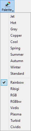 - change the colour palette, including user defined palettes, for the 3D radiation pattern display
![]() - switches on/off isotropic view for the display
- switches on/off isotropic view for the display
![]() - resets display to the default view
- resets display to the default view
![]() - opens Background Colour dialogue for setting the background solid colour or background gradient colours of the display
- opens Background Colour dialogue for setting the background solid colour or background gradient colours of the display
![]() - opens help for Display tab commands (present chapter)
- opens help for Display tab commands (present chapter)
![]() - shows/hides info table displaying parameters of the calculated 3D radiation pattern
- shows/hides info table displaying parameters of the calculated 3D radiation pattern
![]() - shows/hides Colour Bar widget
- shows/hides Colour Bar widget
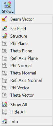
![]() - shows/hides far field radiation pattern plot
- shows/hides far field radiation pattern plot
![]() - shows/hides structure display
- shows/hides structure display
![]() - shows/hides circle plot indicating the Phi angle plane
- shows/hides circle plot indicating the Phi angle plane
![]() - shows/hides circle plot indicating the Theta angle plane
- shows/hides circle plot indicating the Theta angle plane
![]() - shows/hides circle plot indicating the plane containing the reference axis and perpendicular to the Theta angle plane
- shows/hides circle plot indicating the plane containing the reference axis and perpendicular to the Theta angle plane
![]() - shows/hides an axis of Cartesian coordinates system, perpendicular to Phi angle plane
- shows/hides an axis of Cartesian coordinates system, perpendicular to Phi angle plane
![]() - shows/hides an axis of Cartesian coordinates system, perpendicular to Theta angle plane
- shows/hides an axis of Cartesian coordinates system, perpendicular to Theta angle plane
![]() - shows/hides an axis of Cartesian coordinates system perpendicular to the reference axis plane (Ref. Axis Plane)
- shows/hides an axis of Cartesian coordinates system perpendicular to the reference axis plane (Ref. Axis Plane)
![]() - shows/hides Phi angle unit vector
- shows/hides Phi angle unit vector
![]() - shows/hides Theta angle unit vector
- shows/hides Theta angle unit vector
![]() - shows all the above display components
- shows all the above display components
![]() - hides all the above display components
- hides all the above display components
![]() - opens help for Show tab commands (present chapter)
- opens help for Show tab commands (present chapter)
![]() - shows/hides project structure display
- shows/hides project structure display
![]() - loads project structure
- loads project structure
![]() - switches between wire and solid project structure display
- switches between wire and solid project structure display
![]() - opens Structure Blend dialogue for translucency effects for solid project structure display
- opens Structure Blend dialogue for translucency effects for solid project structure display
![]() - opens Structure Zoom dialogue for setting zoom of the project structure display
- opens Structure Zoom dialogue for setting zoom of the project structure display
![]() - shows/hides non-geometrical simulation objects like ABC wall/box and NTF box
- shows/hides non-geometrical simulation objects like ABC wall/box and NTF box
![]() - opens help for Structure tab commands (present chapter)
- opens help for Structure tab commands (present chapter)
![]() - saves 3D radiation pattern results to the *.an3 file
- saves 3D radiation pattern results to the *.an3 file
![]() - exports 3D radiation pattern results to the *.sat file
- exports 3D radiation pattern results to the *.sat file
![]() - saves the current display as a picture to the *.bmp, *.jpg or *.png file
- saves the current display as a picture to the *.bmp, *.jpg or *.png file
![]() - copies the current display to the Clipboard
- copies the current display to the Clipboard
![]() - exports the current display to the *.bmp file
- exports the current display to the *.bmp file
![]() - exports the current display to the *.jpg file
- exports the current display to the *.jpg file
![]() - exports the current display to the *.png file
- exports the current display to the *.png file
![]() - exports the current display to the *.tif file
- exports the current display to the *.tif file
![]() - loads 3D radiation pattern results from the *.an3 file
- loads 3D radiation pattern results from the *.an3 file
![]() - opens help for Export tab commands (present chapter)
- opens help for Export tab commands (present chapter)
 - shows/hides 3D radiation pattern display components. See Show for more information.
![]() - opens Patch Antenna Array dialogue for checking patch antenna parameters (excitations’ amplitude and delay values)
- opens Patch Antenna Array dialogue for checking patch antenna parameters (excitations’ amplitude and delay values)
![]() - shows/hides patch antenna array structure
- shows/hides patch antenna array structure
![]() - shows/hides distribution of excitation amplitudes across the patch array
- shows/hides distribution of excitation amplitudes across the patch array
![]() - shows/hides distribution of excitation delays across the patch array
- shows/hides distribution of excitation delays across the patch array
![]() - shows/hides a vector indicating direction of main radiation beam as set by the user in Patch Antenna Array module of QW-Modeller for QuickWave
- shows/hides a vector indicating direction of main radiation beam as set by the user in Patch Antenna Array module of QW-Modeller for QuickWave
![]() - opens help for Antenna Array tab commands (present chapter)
- opens help for Antenna Array tab commands (present chapter)