2.16 Application of AMIGO
Automatic Meshing Intelligent Generation Option (AMIGO) is a feature enabling automatic FDTD mesh generation taking into account the media parameters of objects present in the project.
Examples of QW-3D applications presented so far in Sections S-parameter extraction problems to QW-OptimiserPlus examples have been prepared before AMIGO and that is why they contain no reference to AMIGO meshing. This Section fills the gap. We suggest the following learning path of AMIGO application:
- read present Section with possible cross checking of the information provided here with the information provided in User Interface of QW-Editor,
- try to apply AMIGO in other standard examples described in Sections S-parameter extraction problems to QW-OptimiserPlus examples.
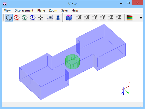
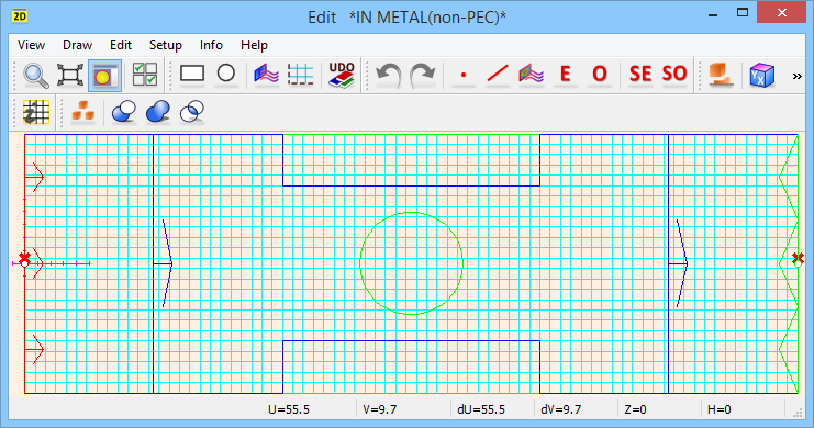
Fig. 2.16-1 Structure of dielf1a example in a 3D window (upper) and in a 2D window showing standard meshing with a cell size of 0.8 mm (lower).
Consider Standard\Filters\Dielf\dielf1a.pro example. It has been prepared using elib/examples/dielf1.udo. It concerns a dielectric resonator placed in a rectangular waveguide (Fig. 2.16-1). The cylindrical resonator made of a medium ep5 (of permittivity 5) is placed in a section of the guide of smaller width. The structure will be analysed up to the frequency of 15 GHz. At that frequency the wavelength is equal to 20 mm in air and to 8.94 mm in the dielectric. Fig. 2.16-1 shows the structure uniformly meshed with a cell size of 0.8 mm, which would be appropriate for analysis in both media. This meshing has been obtained with Mesh Parameters dialogue. To speed-up simulation, we could use a bigger cell size in the entire structure and refine the meshing in the area of the resonator by introducing six mesh-snapping planes around it (Special Planes and Boundaries dialogue) and imposing proper mesh refinement (Edit Special Plane, Boundary dialogue for each mesh snapping plane).
The effect of mesh refinement in the dielectric area can be obtained much easier and faster with the use of AMIGO. This is the case in dielf1b.pro. Press ![]() button in Model tab of QW-Editor to open AMIGOdialogue as in Fig. 2.16-2. The detailed description of the commands and information in this dialogue can be found in AMIGO chapter. Here we will comment only on the key parameters.
button in Model tab of QW-Editor to open AMIGOdialogue as in Fig. 2.16-2. The detailed description of the commands and information in this dialogue can be found in AMIGO chapter. Here we will comment only on the key parameters.
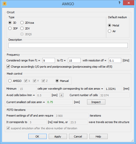
Fig. 2.16-2 AMIGO dialogue for dielf1b example.
The frequency range band of interest has been declared between 9 and 15 GHz, with the required resolution df is equal to 0.15 GHz. This means that we expect no resonances of the double-side band narrower than 0.15 GHz, and we want AMIGO to propose the number of FDTD iterations sufficient for obtaining 0.15 GHz resolution. Through the checkbox in the line below we have requested the band of interest to be automatically transferred to the port settings dialogues (to become the band of excitation of the ports) as well as to the Postprocessing dialogues (to become the band of active post-processings). The frequency step in post-processings will not be 0.15 GHz but 20% of that value (0.03 GHz). The number of the frequency points of the FDTD post-processing has a minor effect on computer time and memory during simulations and thus we can be rather generous in setting the number of frequency points. With the frequency step equal to 20% of the requested frequency resolution we will have full information about the shape of the frequency-dependent characteristics even near the resonant frequencies.
In the central part of the dialogue of Fig. 2.16-2 we have chosen mesh control by AMIGO instead of Manual. In this example, AMIGO meshing is supposed to produce minimum 12 cells per wavelength throughout the structure. It is preferable that geometrical details do not impose mesh-snapping planes separated by a distance smaller than lmin=0.5 mm.
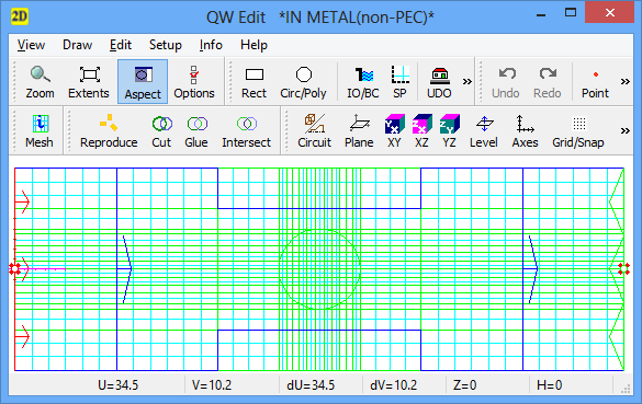
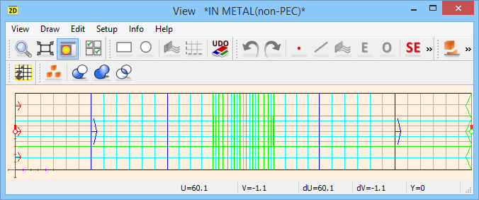
Fig. 2.16-3 AMIGO generated meshing in example dielf1b presented in XY and XZ planes.
The resulting mesh by AMIGO is shown in Fig. 2.16-3. The cylindrical resonator is made of a medium of higher permittivity and thus the mesh is denser in this area to keep the ratio of wavelength to cell size at least 12. Moreover, AMIGO has tried to coordinate the mesh with edges and vertices of elements. For example, since the cylinder has been drawn as a polygon of 30 vertices, soft mesh snapping have been set at its limits and weak mesh snapping planes at its vertices planes (see AMIGO chapter for explanations of mesh-snapping planes priorities). Then the weak mesh snapping planes situated closer that lmin=0.5 mm have been deleted. These operations produced meshing close to optimum within the requested constraints, as presented in Fig. 2.16-3. The smallest cell produced by AMIGO is 0.38196 mm. This is bigger than half of lmin and thus is displayed in the AMIGO dialogue of Fig. 2.16-2 in green, indicating a normal situation.
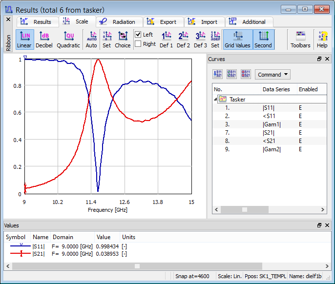
Fig. 2.16-4 Results of simulations of dielf1b example.
In the lower FDTD iterations part of the dialogue, the software suggests 4600 iterations as sufficient for obtaining the desired frequency resolution df. This corresponds to 3.33 ns of the physical time, and is 15.7 bigger than the time needed by a wave in air to travel along the entire structure. Note that the number of FDTD iterations depends on the physical time needed to obtain the proper convergence of the physical processes, and also on the time step dt of the FDTD algorithm. The value of dt chosen by the software is proportional to the value of the current smallest cell size amin. Thus when amin decreases, the physical simulation time needed stays unchanged but the required number of FDTD iterations increases. The last checkbox in the FDTD iterations block instructs QW‑Simulator to suspend after the suggested number of iterations (4600).
Press ![]() button in Simulation tab of QW-Editor to start simulations. After 4600 iterations the simulation is suspended indeed. We obtain well converged results of S11 and S21 as presented in Fig. 2.16-4.
button in Simulation tab of QW-Editor to start simulations. After 4600 iterations the simulation is suspended indeed. We obtain well converged results of S11 and S21 as presented in Fig. 2.16-4.
In Automatic Meshing the classes of mesh snapping planes priorities are formally described. Let us try to introduce some hard mesh snapping planes. Open example dielf1c.pro. Press ![]() button in 2D Window, double-click over element wg and press the right mouse button. The Element Change dialogue of Fig. 2.16-5 appears. It shows that the wg element (the waveguide) has got Amigo status of hard edges. Thus AMIGO generates hard mesh snapping planes along the edges. Edges are understood by AMIGO as straight-line segments along the main axes X, Y or Z, except for the edges aligned with the limits of the meshing area or ports. Hard means that mesh-snapping lines along the waveguide edges will have a high priority, and will not be automatically removed by AMIGO. Moreover, weak mesh snapping planes are generated at a distance lmin on both sides of the hard plane. This is exemplified in Fig. 2.16-6.
button in 2D Window, double-click over element wg and press the right mouse button. The Element Change dialogue of Fig. 2.16-5 appears. It shows that the wg element (the waveguide) has got Amigo status of hard edges. Thus AMIGO generates hard mesh snapping planes along the edges. Edges are understood by AMIGO as straight-line segments along the main axes X, Y or Z, except for the edges aligned with the limits of the meshing area or ports. Hard means that mesh-snapping lines along the waveguide edges will have a high priority, and will not be automatically removed by AMIGO. Moreover, weak mesh snapping planes are generated at a distance lmin on both sides of the hard plane. This is exemplified in Fig. 2.16-6.
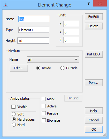
Fig. 2.16-5 Element Change dialogue of dielf1c example defining hard edges of the waveguide element.
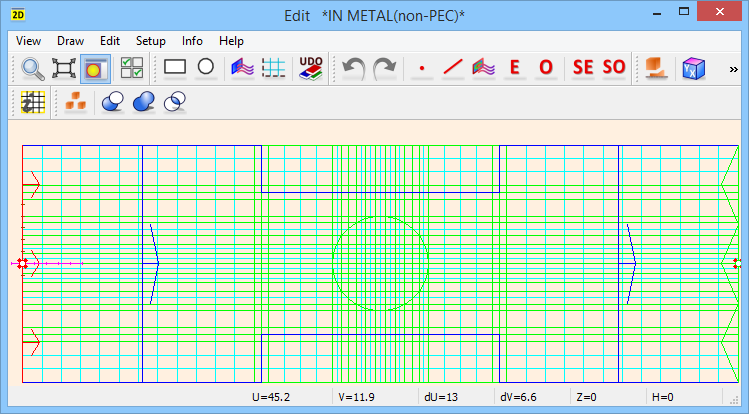
Fig. 2.16-6 Meshing obtained with the waveguide of hard edges.
It can be verified that AMIGO meshing of dielf1b is sufficient for very good accuracy and introducing hard edges of the waveguide, as in dielf1c.pro, does not change much. However, there are cases when hard edges may bring substantial accuracy improvement. A practical example is that of microstrip simulations, where hard mesh snapping planes activate field singularity models along strip edges and thus provide accurate characteristic impedance of the line even with meshing as rough as 2-3 cells per strip width.