5.2.1 Basic Join operations
Let us consider an example structure of .\Various\Joinex\jo1.pro. It is composed of two UDO objects, each producing one element: a cylinder made of metal (cyvo.udo) and a parallelepiped made of quartz (solid.udo). Both elements are of the same height and are intersecting each other. Thus the structure is not well defined because there is no indication which of the medium prevails in the common part of the structure.
The structure obtained in QW‑Editor’s 3D Window with wireframe view (a) and 3D Window with solid view (b) windows, SAT files Viewer (c), and QW-Simulator’s Test Mesh [![]() ] window (d). It is visible that there is some confusion about the actual shape. The picture in the 3D solid view may depend on the order of elements in the QW-Editor’s list. SAT files Viewer cannot decide about the actual shape. But most important is that the meshing produced in QW-Simulator is confused.
] window (d). It is visible that there is some confusion about the actual shape. The picture in the 3D solid view may depend on the order of elements in the QW-Editor’s list. SAT files Viewer cannot decide about the actual shape. But most important is that the meshing produced in QW-Simulator is confused.
a) b)
b)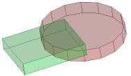 c)
c)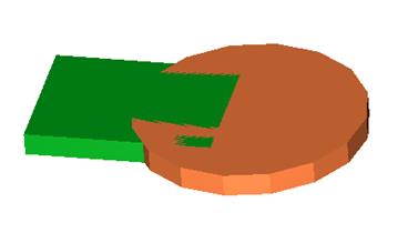 d)
d) 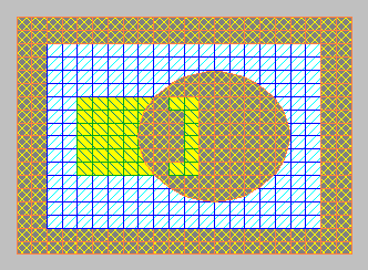
The structure of jo1.pro visualised in: a) 3D Window with wireframe view, b) 3D Window with solid view, c) SAT files Viewer, d) QW-Simulator’s Test Mesh window.
In this case to produce a correct structure we must use Join operations. Let us assume that quartz is the medium to prevail in the common space. Thus we invoke Select Object dialogue and on the appearing list of objects Mark for Join solid.udo as active and cyvo.udo as passive. This operation will mark all the elements belonging to solid.udo as active and all the elements belonging to cyvo.udo as passive. We can verify that by pressing Select Element dialogue to watch in the list of elements those marked with letters A and P. Note that in general the Boolean operations in QW‑Editor will be performed on elements and that the objects will serve only to mark groups of elements.
Let us now try to invoke Join and perform consecutively each of the available options (followed by Undo and Mark for Join operations before tying the next option).
a)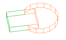 b)
b)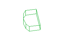 c)
c)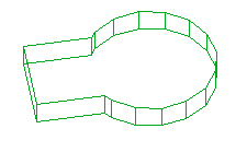
d) 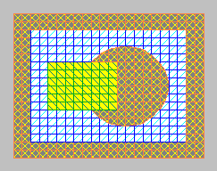 e)
e) 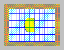 f)
f) 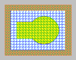
The structures resulting from Boolean operations on jo1.pro with Cut (a), Intersect (b) and Glue (c) as well as the Test Mesh pictures in each of the cases (d, e, f).
Note that:
· After calling Select Object following Glue operation we can find that the original UDO objects have disappeared and we have now one object called glue. Thus we do not have now the access to the headers of the original UDOs and the possibility to modify the dimensions of the structure. To maintain such a possibility we would need to prepare a new UDO incorporating calls to both original UDOs and the Glue operation.
· After Glue operation the elements belonging to the new object named glue have inherited the medium from the active elements. In fact they also inherit other attributes like that of being biphased or enforcing E-plane or N- plane on its bottom and top. This effect will be further discussed in Join operations on combined elements chapter.
Let us now consider the example jo2.pro. With respect to jo1.pro there is only one difference: the parallelepiped (solid.udo) has been moved down by 0.5 mm. Let us perform the Cut operation the same way we did it with jo1.pro. The structure has been divided into 3 slices. In the lower slice we have only the lower part of solid, in the upper slice – only the upper part of cyvo. In the middle slice we have the upper part of solid and the lower part of cyvo modified by the Cut operation. Please consult the list in the Select Element dialogue list to see four elements, which have been created. You can also try to select any of them and move it in a 2D Window to see better its shape and position with respect to other elements.
a) 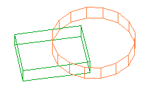 b)
b)
The structure of example jo2.pro before (a) and after the Cut operation.