7.5 Mesh Info
The ![]() button in Model tab and Mesh->FDTD Mesh Info... command from main menu invoke Mesh/Splanes Info dialogue.
button in Model tab and Mesh->FDTD Mesh Info... command from main menu invoke Mesh/Splanes Info dialogue.
The ![]() button in the 2D Window toolbar and Info->FDTD Mesh... command from 2D Window menu invoke Mesh/Splanes Info dialogue.
button in the 2D Window toolbar and Info->FDTD Mesh... command from 2D Window menu invoke Mesh/Splanes Info dialogue.
The Mesh/Splanes Info dialogue can be also invoked from Mesh Parameters dialogue.
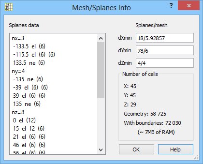
This dialogue permits to see the list of all mesh snapping planes and the minimum distance between the neighbouring planes (on the right of the box). This permits to spot the planes very close to one another. Such planes would produce very small FDTD cells. Since the step in time of the FDTD analysis must be adjusted to the smallest cell (Courant stability criterion), existence of very small cells can drastically slow down the simulation process. Thus small cells should be avoided whenever not absolutely necessary for correct space approximation of the analysed structure. Since during the editing process the user can unintentionally introduce very small cells, we recommend as a good habit consulting the list of mesh snapping planes any time after important changes in the structure have been made.
On the left hand side of this window we can see all the special planes, which may have been created in the following ways:
· set explicitly by the user (via the Special Planes and Boundaries dialogue, Snapping Plane dialogue or corresponding UDO commands),
· enforced by edges (outermost boundaries of the circuit),
· enforced by ports,
· introduced by the software at the level of bottom and cover of each element, following the user's specification of Bottom/top kind of this element in the Define Level dialogue,
· introduced by Amigo (if active) at edges or corners of each element, following the user's specification of Amigo status of this element in the Element Change.
The information visible in the Splanes data includes:
· number of the mesh snapping planes nx, ny, nz for X, Y, Z respectively.
· nocation of each mesh snapping planes.
· type: el denotes electric or short, which forces a plane of tangential electric fields (and thus contains the cell sides); ma denotes magnetic or open, which forces a plane of tangential magnetic fields (and thus bisects the cells); ne denotes neutral, which may coincide with either tangential electric or tangential magnetic fields. Note that suspended planes are listed in a separate section following the nsuspz header.
· cell size forced in the negative and positive directions from the special plane. If the user has explicitly defined the forced cell size when drawing or editing this particular special plane, this value will be shown without brackets, and supersede all defaults. However, if the user has not made such an explicit setting, the forced cell size will be inherited from the settings of other special planes, and it will be shown in brackets. If the forced cell size has been explicitly defined for two special planes located in the plus- and minus- direction from the considered plane, respectively, the forced cell size for this considered plane will be calculated by linear interpolation from the two forced cell sizes of its two neighours, wieghtd by its respective distances from these neighbours. This opens way to the construction of a linearly varying mesh. Remember that the edges of the circuit take part in the algorithm if the Edges force linear mesh box is checked. If number 0 appears as the forced cell size, it means that a particular special plane does not force any specific cell size – it is transparent to mesh control performed by other special planes.
The information visible in the Splanes/mesh includes minimum values of the distances between the neighbouring special planes, versus minimum cell size in each direction. If these two numbers coincide, it is an indication that two mesh snapping planes may be very close to each other and may effectively control the FDTD time step.
The Number of cells includes number of cells that have been created in the QW-Editor and how many of them will appear in the QW-Simulator (including the cells needed to model the boundary effects). This number is crucial for judging if we have sufficient amount of memory to run this example with this meshing, and how long the simulation will take.