Parallel plate transmission line
The present example considers a parallel plate transmission line.
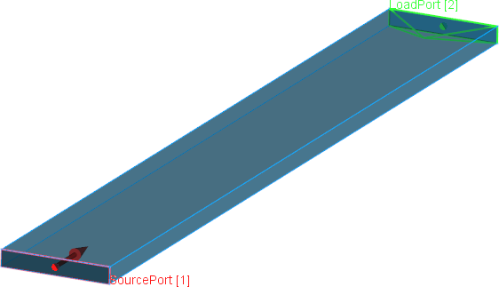
Parallel plate transmission line.
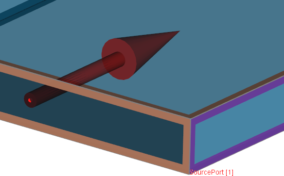
Parallel plate transmission line - violet colour on the both sides indicates PMC boundary conditions.
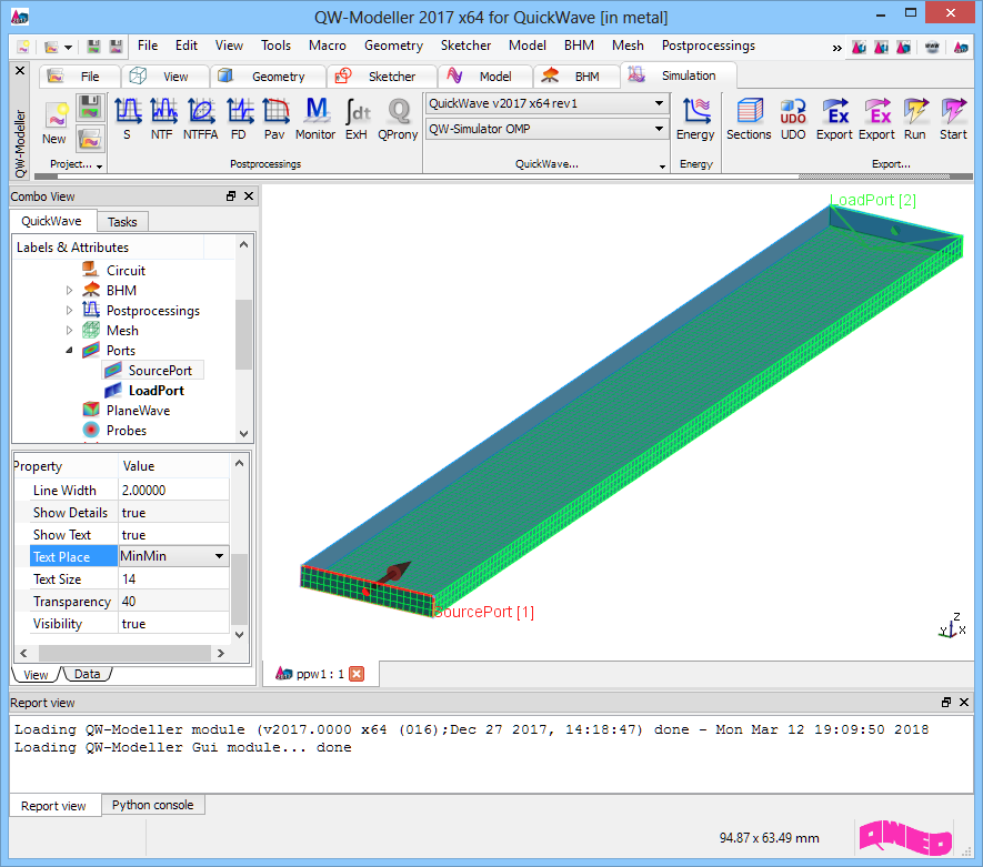
Parallel plate transmission line project in QW-Modeller.
Simulation model presents parallel plate transmission line (violet colour on the both sides indicates PMC boundary conditions) excited with a plane wave (red transmission line port) and terminated with a load port (green transmission line port) matched to the line. The transmission line is filled with air.
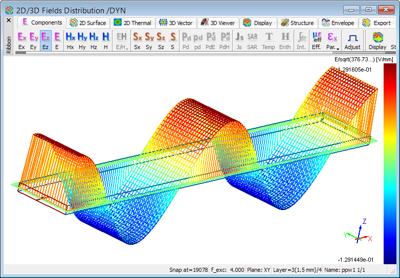
Ez field component distribution at 4GHz.
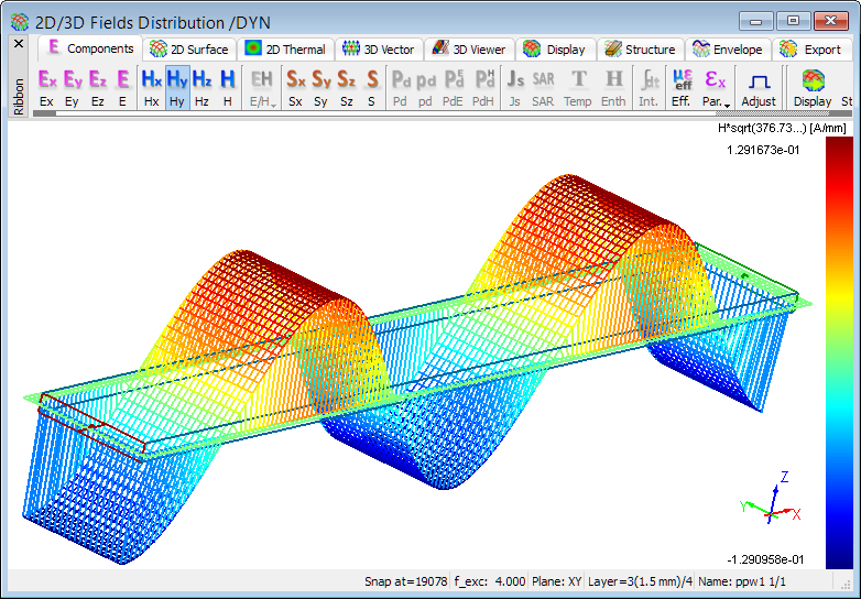
Hy field component distribution at 4GHz.
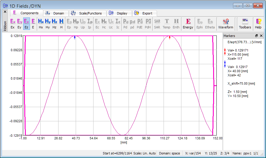
1D view of Ez field component distribution at 4GHz (instantaneous and envelope values).
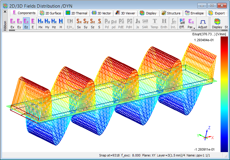
Ez field component distribution at 8GHz.
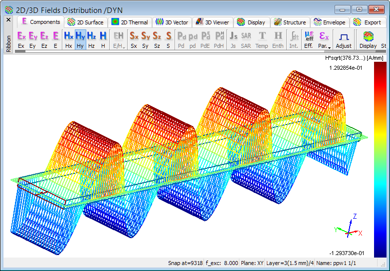
Hy field component distribution at 8GHz.
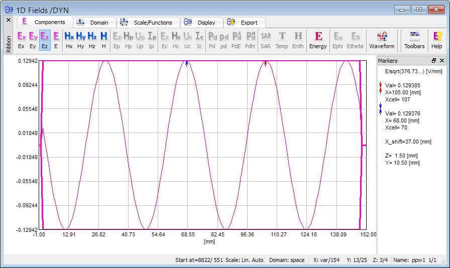
1D view of Ez field component distribution at 8GHz (instantaneous and envelope values).
Lossy medium
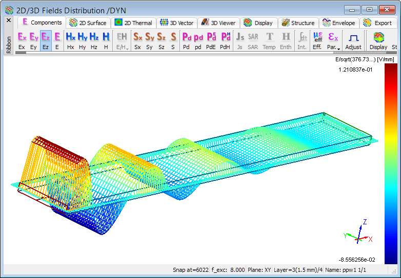
Ez field component distribution in lossy medium at 8GHz.
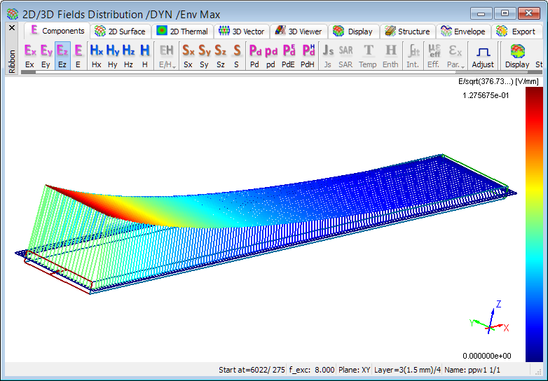
Time-maximum envelope of Ez field component distribution in lossy medium at 8GHz.
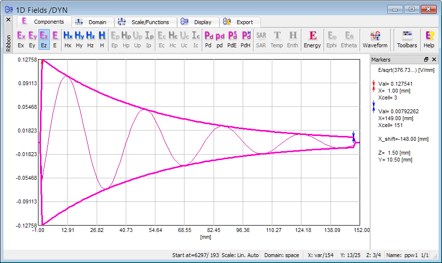
1D view of Ez field component distribution in lossy medium at 8GHz (instantaneous and envelope values).